Überblick
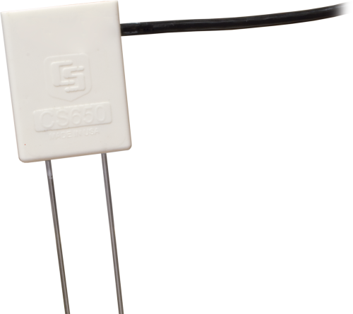
Der CS655 ist ein Multiparametersensor der mit Hilfe einer innovativen Technik den volumetrischen Wassergehalt, elektrische Leitfähigkeit und Temperatur des Bodens bestimmt. Er gibt ein SDI-12 Signal aus, das von fast allen unseren Loggern gelesen werden kann. Er hat kürzere Stäbe als der CS650 zum Einsatz in schwierigeren Böden.
Lesen Sie mehrFunktionen und Vorteile
- Größeres Probenvolumen reduziert Fehler
- Messwerte werden korrigiert zur Vermeidung von Effekten durch verschiedene Bodenarten und elektrische Leitfähigkeiten
- Kalkuliert Badenwassergehalt für viele mineralische Böden
- Vielseitiger Sensor, misst elektrische Leitfähigkeit, volumetrischen Wassergehalt, Dielektrizitätskonstante und Temperatur
Bilder
Zugehörige Produkte


Technische Beschreibung
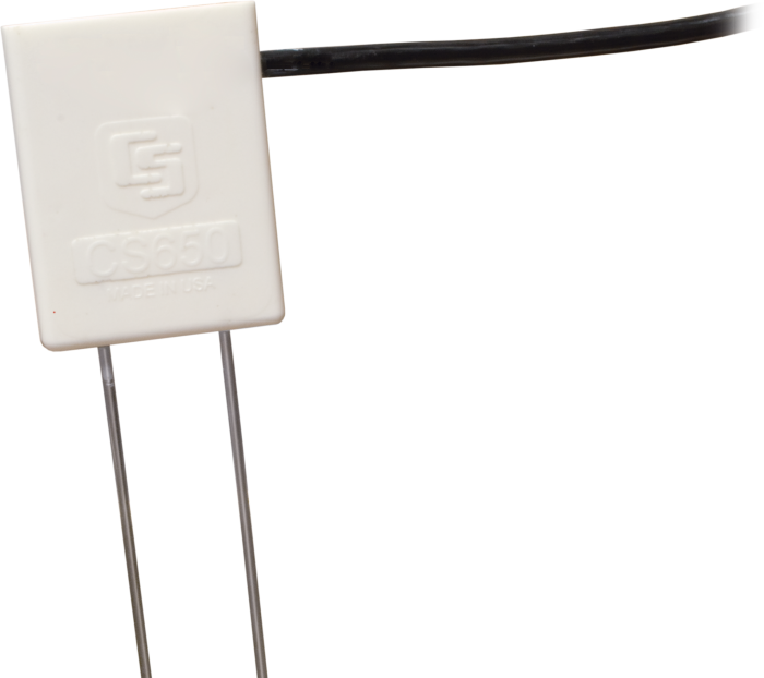
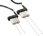
The CS655 consists of two 12-cm-long stainless steel rods connected to a printed circuit board. The circuit board is encapsulated in epoxy and a shielded cable is attached to the circuit board for data logger connection.
The CS655 measures propagation time, signal attenuation, and temperature. Dielectric permittivity, volumetric water content, and bulk electrical conductivity are then derived from these raw values.
Measured signal attenuation is used to correct for the loss effect on reflection detection and thus propagation time measurement. This loss-effect correction allows accurate water content measurements in soils with bulk EC ≤8 dS m-1 without performing a soil-specific calibration.
Soil bulk electrical conductivity is also calculated from the attenuation measurement. A thermistor in thermal contact with a probe rod near the epoxy surface measures temperature. Horizontal installation of the sensor provides accurate soil temperature measurement at the same depth as the water content. Temperature measurement in other orientations will be that of the region near the rod entrance into the epoxy body.
Kompatibel mit
Please note: The following shows notable compatibility information. It is not a comprehensive list of all compatible products.
Datenlogger
| Product | Compatible | Note |
|---|---|---|
| CR1000 (retired) | ||
| CR1000X (retired) | ||
| CR300 (retired) | ||
| CR3000 | ||
| CR310 | ||
| CR350 | ||
| CR6 | ||
| CR800 (retired) | ||
| CR850 (retired) |
Additional Compatibility Information
RF Considerations
External RF Sources
External RF sources can affect the probe’s operation. Therefore, the probe should be located away from significant sources of RF such as ac power lines and motors.
Interprobe Interference
Multiple CS655 probes can be installed within 4 inches of each other when using the standard data logger SDI-12 “M” command. The SDI-12 “M” command allows only one probe to be enabled at a time.
Optional Installation Tool
CS650G Rod Insertion Guide Tool
The CS650G makes inserting soil-water sensors easier in dense or rocky soils. This tool can be hammered into the soil with force that might damage the sensor if the CS650G was not used. It makes pilot holes into which the rods of the sensors can then be inserted.
Spezifikationen
| Measurements Made | Soil electrical conductivity (EC), relative dielectric permittivity, volumetric water content (VWC), soil temperature |
| Required Equipment | Measurement system |
| Soil Suitability | Short rods are easy to install in hard soil. Suitable for soils with higher electrical conductivity. |
| Rods | Not replaceable |
| Sensors | Not interchangeable |
| Sensing Volume | 3600 cm3 (~7.5 cm radius around each probe rod and 4.5 cm beyond the end of the rods) |
| Electromagnetic | CE compliant (Meets EN61326 requirements for protection against electrostatic discharge and surge.) |
| Operating Temperature Range | -50° to +70°C |
| Sensor Output | SDI-12; serial RS-232 |
| Warm-up Time | 3 s |
| Measurement Time | 3 ms to measure; 600 ms to complete SDI-12 command |
| Power Supply Requirements | 6 to 18 Vdc (Must be able to supply 45 mA @ 12 Vdc.) |
| Maximum Cable Length | 610 m (2000 ft) combined length for up to 25 sensors connected to the same data logger control port |
| Rod Spacing | 32 mm (1.3 in.) |
| Ingress Protection Rating | IP68 |
| Rod Diameter | 3.2 mm (0.13 in.) |
| Rod Length | 120 mm (4.7 in.) |
| Probe Head Dimensions | 85 x 63 x 18 mm (3.3 x 2.5 x 0.7 in.) |
| Cable Weight | 35 g per m (0.38 oz per ft) |
| Probe Weight | 240 g (8.5 oz) without cable |
Current Drain |
|
| Active (3 ms) |
|
| Quiescent | 135 µA typical (@ 12 Vdc) |
Electrical Conductivity |
|
| Range for Solution EC | 0 to 8 dS/m |
| Range for Bulk EC | 0 to 8 dS/m |
| Accuracy | ±(5% of reading + 0.05 dS/m) |
| Precision | 0.5% of BEC |
Relative Dielectric Permittivity |
|
| Range | 1 to 81 |
| Accuracy |
|
| Precision | < 0.02 |
Volumetric Water Content |
|
| Range | 0 to 100% (with M4 command) |
| Water Content Accuracy |
|
| Precision | < 0.05% |
Soil Temperature |
|
| Range | -50° to +70°C |
| Resolution | 0.001°C |
| Accuracy |
|
| Precision | ±0.02°C |
Dokumente
Broschüren Produkte
Technische Artikel
Realisierte Projekte
Übereinstimmung mit Richtlinien u. Vorschriften



FAQs für
Number of FAQs related to CS655: 51
Alle anzeigenWenige anzeigen
-
If a system has multiple CS650 or CS655 sensors, it will be necessary to connect many wires to a 12 V supply and many wires to ground. The DIN Rail Mounting Kit is useful for attaching many wires to the same source in a clean and organized way. For more details, see the 5458 DIN Rail Terminal Kit instruction manual.
Other methods of connecting several wires together, such as terminal strips or wire nuts, would also work.
-
The volumetric water content reading is the average water content over the length of the sensor’s rods.
-
Campbell Scientific strongly discourages shortening the sensor’s rods. The electronics in the sensor head have been optimized to work with the 12 cm long rods. Shortening these rods will change the period average. Consequently, the equations in the firmware will become invalid and give inaccurate readings.
-
The CS650-series sensors have the same rugged epoxy and stainless-steel rods that have been used for water content reflectometers since the CS615-L model was introduced in 1995. There are CS615-L and CS616 sensors in many locations that have been in continuous use for more than ten years with no reported problems. If a CS650 or CS655 remains undamaged by external forces such as lightning, harsh chemicals, or animal actions, the sensor is expected to continue working for decades.
-
Both the CS650 and the CS655 can detect water as far away as 10 cm in wet sand. That distance decreases as the soil dries down to approximately 4 cm in dry sand. In practice, a depth of 5 cm will give a water content reading that is within the sensor accuracy specification even if a small amount of air near the soil surface is detected and averaged into the reading.
Note: Campbell Scientific does not recommend installing the sensor in a depth shallower than 5 cm.
-
Yes. Keeping the sensor rods parallel during installation is especially difficult in gravel, but it can be done. Gravel has large pore spaces that drain quickly, so the water content readings will likely show rapid changes between saturation and very dry. If small changes of water content at the dry end are of interest, a soil-specific calibration may need to be performed to convert period average directly to volumetric water content.
-
The permittivity of saturated sediments in a stream bed is expected to read somewhere between 25 and 42, while the permittivity of water is close to 80. A CS650 or CS655 installed in saturated sediments could be used to monitor sediment erosion. If the permittivity continuously increases beyond the initial saturated reading, this is an indication that sediment around the sensor rods has eroded and been replaced with water. A calibration could be performed that relates permittivity to the depth of the rods still in the sediment.
-
The CS650 and the CS655 are not ideal sensors for measuring water level. However, these sensors do respond to the abrupt change in permittivity at the air/water interface. A calibration could be performed to relate the period average or permittivity reading to the distance along the sensor rods where the air/water interface is located. From that, the water level can be determined. The permittivity of water is temperature dependent, so a temperature correction would be needed to acquire accurate results.
-
No. It is not possible to disable the logical tests in the firmware. If soil conditions cause frequent NAN values, it may be possible to perform a soil-specific calibration that will provide good results.
If permittivity is reported but the volumetric water content value is NAN, Campbell Scientific recommends a soil-specific calibration that converts permittivity to water content. This will take advantage of the bulk electrical conductivity correction that occurs in the firmware.
If both permittivity and volumetric water content have NAN values, it may be possible to perform a calibration that converts period average directly to volumetric water content.
For details on performing a soil-specific calibration, refer to “The Water Content Reflectometer Method for Measuring Volumetric Water Content” section in the CS650/CS655 manual. After a soil-specific equation is determined, it may be programmed into the data logger program or used in a spreadsheet to calculate the soil water content.
-
Three of the values returned by the M3! command are never changed to NAN by logical tests. If non-zero readings for soil temperature, period average, and voltage ratio are displayed, the sensor is working.
A simple test in air and water will also show whether the CS650 or CS655 is functioning. When performing this test, look at the permittivity value and not the water content value. In air, the sensor will read a permittivity value of 1. In room-temperature water, the value should be close to 80. The water container should have a diameter of at least 20 cm (8 in.) and a depth of 33 cm (13 in.). A smaller container will result in a lower permittivity value because the sensor will be measuring some of the air outside the container as well as the water. Tap water is acceptable for this test.
Anwendungsbeispiele

At the northern edge of Jamaica, fresh water from a limestone aquifer and the Martha......lesen Sie mehr