This product is not available for new orders. We recommend ordering: CR1000X.

| Services Available | |
|---|---|
| Repair | Yes |
| Calibration | Yes |
| Free Support | No |
Überblick
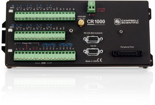
Der CR1000 ist unser meistverkaufter Datenlogger. Basierend auf dem ist er ist zuverlässig, robust und sehr flexibel. Der CR1000 verfügt über 4MB internen Speicher für Daten und Programme, durch ein CompactFlash-Modul kann der Speicherplatz noch erweitert werden.
Es sind verschiedene Arten der Datenübertragung möglich wie Ethernet, GSM, GPRS, Funk usw. Auch ein abnehmbares Display, das CR1000KD kann zu den Stationen mitgenommen werden.
Lesen Sie mehrFunktionen und Vorteile
- Ideal applications include fire weather, mesonet systems, wind profiling, weather stations, air quality, ETo/agriculture, soil moisture, water level/stage, aquaculture, avalanche forecasting, time-domain reflectometry, vehicle testing, SCADA, and water quality
- Serial communications with serial sensors and devices supported via I/O port pairs
- Collects and stores data and controls peripherals as the brain of your system
- Flexible power and communication options make it ideal for remote locations.
- 4-MB memory can be expanded with add-on memory systems.
- Supports PakBus, Modbus, SDI-12, and DNP3 protocols
- Compatible with channel expansion peripherals allowing you to expand your system
- Program with LoggerNet, PC400, or Short Cut to fit your setup
- Communicates via various options: TCP/IP, email, FTP, web server.
- Gas Discharge Tube (GDT) protected inputs
- Battery-backed clock that ensures accurate time is maintained while data logger is disconnected from battery power
- Program and control on site with addition of CR1000KD keyboard and display unit.
- Contains custom ASIC chip that expands pulse count, control port, and serial communications capabilities
Bilder


3D/CAD-Dateien:
Technische Beschreibung
Der CR1000 besteht aus der Mess- und Steuereinheit und der Anschlussleiste. Durch seinen geringen Stromverbrauch kann er über lange Zeiträume mit einer Batterie, die mit Solarzellen wieder aufgeladen wird, arbeiten. Fällt die Spannung unter 9,6V, setzt der CR1000 mit den Messungen aus um ungenaue Werte zu vermeiden. Der CR1000 kann mit einer externen Tastatur mit Display, dem CR1000KD kombiniert werden, um Status und Messwerte zu überprüfen und Einstellungen zu machen. Der kompakte und leichte Logger hat eine Programm-Ausführungsrate von 100 Hz und 1500 Hz im Burst-Mode. Er enthält einen 16-bit H8S Hitachi Mikrokontroller mit interner 32-bit CPU-Architektur. Acht differentielle (16 single-ended) analoge Eingänge, zwei Pulszähler und acht digitale I/O-Ports werden durch CS I/O- und RS-232 Port, einen 40-pin peripheren Anschluss und eine Ethernet-Option komplettiert.
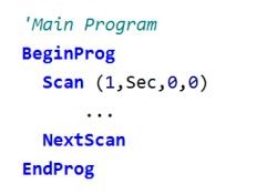
Kommunikation: Der CR1000 ist kompatibel mit allen Kommunikationmöglichkeiten wie GSM, GPRS, Funk, Satellit und Ethernet. Das PakBus Betriebssystem erleichtert die Datensammlung in Logger-Netzwerken. Zusätzlich besteht die Möglichkeit zum Anschluss mehrerer SDM's in verschiedenen Kombinationen, so dass für praktisch jede Anwendung eine Lösung gefunden werden kann. Der Logger wird über CR-BASIC programmiert, eine BASIC-ähnliche Programmiersprache, für einfache Anwendungen reicht auch der freie visuelle Editor Shortcut.
Standardmäßig seit September 2007 (SN 11832 oder höher) mit 4MB Speicher ausgestattet, ist durch die neuen CompactFlash-Speichermodule eine problemlose Erweiterung auf bis zu 2GB möglich.
Kompatibel mit
Please note: The following shows notable compatibility information. It is not a comprehensive list of all compatible products.
Peripheriegeräte
| Product | Compatible | Note |
|---|---|---|
| SDM-SIO2R |
Software
| Product | Compatible | Note |
|---|---|---|
| LoggerNet | Version 3.0 or higher | |
| PC200 (retired) | ||
| PCONNECT (retired) | Version 3.1 or higher | |
| PCONNECTCE (retired) | Version 2.0 or higher | |
| RTDAQ | Version 1.0 or higher | |
| Short Cut |
Miscellaneous
| Product | Compatible | Note |
|---|---|---|
| PC400 | Version 1.2 or higher |
Additional Compatibility Information
Sensors
With several channel types, the CR1000 is compatible with nearly every available sensor, including thermocouples, SDI-12 sensors, and 4 to 20 mA sensors (via a terminal input module, such as the CURS100). A custom ASIC chip expands its pulse count, control port, and serial communications capabilities. The CR1000's I/O ports can be paired as transmit and receive, allowing serial communications with serial sensors and devices.
Measurement & Control Peripherals
The CR1000 is compatible with all of our CDMs (requires an SC-CPI), SDMs, multiplexers, vibrating-wire interfaces, terminal input modules, and relays.
Communications
The CR1000 communicates with a PC via direct connect, Ethernet interfaces, multidrop modems, short-haul modems, phone modems (land line, digital cellular, and voice-synthesized), RF telemetry, and satellite transmitters (Argos, Iridium, and Inmarsat).
Data can be viewed on the CR1000KD Keyboard Display, the CD100 Mountable Display with Keyboard, an iOS or Android device (requires LoggerLink), CD295 DataView II Display, or a user-supplied PDA (PConnect or PConnectCE software required).
Compatible external data storage devices are the CFM100, NL115, and SC115.
Enclosures
The CR1000 and its power supply can be housed in any of our standard enclosures.
Power
Any 12 Vdc source can power the CR1000 datalogger. Power supplies commonly used with the CR1000 are the BPALK, PS150, and PS200. The BPALK provides eight non-rechargeable D-cell alkaline batteries with a 7.5 Ah rating at 20°C.
Both the PS150 and PS200 consist of a sealed rechargeable 7 Ah battery and a charging regulator. Their battery should be connected to a charging source (either a wall charger or solar panel). These two power supplies differ in their charging regulator. The PS150 has a standard regulator and the PS200 has a micro-controller-based smart regulator. The PS200's regulator provides two-step constant voltage charging and temperature compensation that optimize battery charging and increases the battery’s life.
Also available are the BP12 and BP24 battery packs, which provide nominal ratings of 12 and 24 Ah, respectively. These batteries should be connected to a regulated charging source (e.g., a CH100 or CH200 connected to a unregulated solar panel or wall charger).
Software
CRBasic, the CR1000's full programming language, supports simple or complex programming and many onboard data reduction processes. Compatible software includes:
- Short Cut
- PC200W
- PC400 (version 1.2 or higher)
- LoggerNet (version 3.0 or higher)
- RTDAQ (version 1.0 or higher)
- PConnect (version 3.1 or higher)
- PConnectCE (version 2.0 or higher)
- VisualWeather (version 2.0 or higher)
Spezifikationen
| -NOTE- | Additional specifications are listed in the CR1000 Specifications Sheet. |
| Operating Temperature Range |
|
| Analog Inputs | 16 single-ended or 8 differential (individually configured) |
| Pulse Counters | 2 |
| Voltage Excitation Terminals | 3 (VX1 to VX3) |
| Communications Ports |
|
| Switched 12 Volt | 1 terminal |
| Digital I/O |
|
| Input Limits | ±5 Vdc |
| Analog Voltage Accuracy | ±(0.06% of reading + offset) at 0° to 40°C |
| ADC | 13-bit |
| Power Requirements | 9.6 to 16 Vdc |
| Real-Time Clock Accuracy | ±3 min. per year (Correction via GPS optional.) |
| Internet Protocols | FTP, HTTP, XML, POP3, SMTP, Telnet, NTCIP, NTP |
| Communication Protocols | PakBus, Modbus, DNP3, SDI-12, SDM |
| Warranty | 3 years |
| Battery-backed SRAM for CPU Usage & Final Storage | 4 MB |
| Idle Current Drain, Average | < 1mA (@ 12 Vdc) |
| Active Current Drain, Average |
|
| Dimensions |
|
| Weight | 1.0 kg (2.1 lb) |
Dokumente
Broschüren Produkte
Handbücher
Technische Artikel
- FTP Streaming
- Benefits of Input Reversal and Excitation Reversal for Voltage Measurements
- Preventing and Attacking Measurement Noise Problems
- DNP3 with Campbell Scientific Dataloggers
- Voltage Accuracy, Self-Calibration, and Ratiometric Measurements
- BACnet to Modbus Protocol Conversion (App. Note: 1M-C)
- AlphaGUARD Radon Monitor Interfaced with the CR1000 Datalogger
- Serial Sensors: Interfacing with CSI Dataloggers (App. Note Code: 2MI-V)
- PC/CF Card Information (3SM-F)
Realisierte Projekte
Übereinstimmung mit Richtlinien u. Vorschriften
Verschiedenes
Videos & Tutorials
Downloads
CR1000 OS v.32.07 (4.60 MB) 15-05-2024
Execution of this download installs the CR1000 Operating System and Compiler on your computer. It also updates the CR1000 support files for the CRBasic Editor.
Note: This OS has crossed the 2 Meg CR1000 size limit for remote download. The OS must be downloaded to the 2 Meg CR1000 via direct connect with the Device Configuration Utility. All OS download methods are supported by the 4 Meg CR1000.
Upgrading from versions prior to version 28 of the Operating System will reset the datalogger’s CPU drive. This is due to a change in the format of the file system from FAT16 to FAT32. In order for the datalogger to operate correctly, as part of the upgrade, the CPU drive is formatted to FAT32. Any programs stored and running from the CPU drive will be lost. It is not recommended to update the datalogger’s Operating System over a remote connection where program control regulates the communication equipment (turning it on or off, etc.). In these cases, an on-site visit and a backup using DevConfig’s backup utility is necessary to update the datalogger’s Operating System.
Watch the Video Tutorial: Sending an OS to a Local Datalogger.
In all cases where the datalogger is being updated from an Operating System prior to 28, the use of DevConfig’s backup utility is recommended due to the CPU drive being formatted using the new FAT32 format.
Device Configuration Utility v.2.32.01 (47.7 MB) 15-04-2025
A software utility used to download operating systems and set up Campbell Scientific hardware. Also will update PakBus Graph and the Network Planner if they have been installed previously by another Campbell Scientific software package.
Supported Operating Systems:
Windows 11 or 10 (Both 32 and 64 bit)
FAQs für
Number of FAQs related to CR1000: 184
Alle anzeigenWenige anzeigen
-
Recalibration of the CR1000 is recommended every three years.
-
The potential transformer and the current transformer provide differential outputs that have galvanic isolation from the voltage and current in the circuit they are measuring. However, there is no need to run the outputs of these transformers into differential inputs of the data logger and unnecessarily consume additional data logger channels. We conducted extensive testing for noise immunity, for inaccuracies from ground loops, and more before concluding that single-ended measurements in the ACPower() instruction have the same performance as differential measurements would provide. Please note that as a result of the galvanic isolation of the potential transformer and current transformer, the data logger ground is NOT connected to the ground of the circuit they are measuring.
Said differently, you can connect differential outputs of a sensor to single-ended inputs of the data logger. However, doing so creates the possibility of poor common-mode noise rejection in the data logger and the possibility of introducing inaccuracies from ground loops between the sensor and the data logger. Note that in this application, the transformer isolation of the potential transformer and the current transformer eliminates these concerns.
Simply connect one of the potential transformer secondary wires and one of the current transformer secondary wires to the data logger ground. Which wire in either case makes a difference, as the phase information allows the measurement of power flowing in either direction. If you measure negative real power when it should be positive, then reverse the secondary wires of the potential transformer where they connect to the data logger. Alternatively, you can reverse the secondary wires on the current transformer, but don't reverse both pairs of wires.
-
The CR1000 and CR1000X will be sold concurrently for no less than two years. We anticipate the CR1000 will be retired in December of 2019 and will be supported until December of 2029.
-
Yes, because HTTP is a separate protocol from PakBus.
-
50 Hz rejection is available for analog voltage measurements by setting the Integration parameter.
-
Yes. Create a multidrop network with an MD485 between the CR5000, the CR1000, and the digital modem. See the “Digital Cellular Modem to MD485 Network” appendix item in the MD485 instruction manual.
-
Only one CWB100 can be connected to each odd channel control port. For the CR800 and CR850, this relates to two total units—one on C1 and one on C3. On the CR1000 and CR3000, this amounts to four total units.
Putting more than one CWB100 on a data logger will NOT speed up sensor data collection. Only one CWB100 should be accessed at any given time, or the devices will interfere with each other. If multiple CWB100 devices are connected to a single data logger, the data collection schedules for the CWB100 devices should be staggered. Sufficient time should be built in to allow each base unit to collect data from all of the remote sensors associated with it and to allow for any needed retries.
-
Sending a serial string out one of the datalogger COM ports requires at least two instructions. Generally, the SerialOpen() instruction is used to set the characteristics of the communications port, such as baud rate and error detection (for example, 115.2k, N, 8, 1). The instructions SerialOut() or SerialOutBlock() can be used to transmit a specified string. See the CRBasic Editor Help for examples of programs using each of these instructions.
-
The datalogger’s Status table has a LastSystemScan field that provides this information.
-
If both data loggers are using the same cellular modem, simultaneous connection and download is not possible. To resolve this, first create a local network, such as by direct connection, RF4xx radios, an MD485, or Ethernet. Then use the cellular modem to access the network.
Anwendungsbeispiele
Tropical volcanic islands are biodiversity hotspots where the Critical Zone (CZ) remains poorly studied. In......lesen Sie mehr
Background In 2022, ECR Medio Ambiente assumed the responsibility of overseeing the structural monitoring installation at......lesen Sie mehr
Overview The Chauvet-Pont d'Arc and Aven d'Orgnac caves are home to prehistoric treasures of rare artistic......lesen Sie mehr
Severe Tropical Cyclone Debbie was a category 4 system that made landfall near Airlie Beach......lesen Sie mehr
Valhalla, an energy company in Chile, is making resource assessment and solar-panel soiling measurements in......lesen Sie mehr
The Warra long-term ecological research (LTER) site located in Southwestern Tasmania was founded in 1995......lesen Sie mehr
Campbell Scientific’s system integrator, AUDIMOBIL LDA, recently upgraded the airport weather system in the S.......lesen Sie mehr
On March 14, 2016, the European Space Agency (ESA) launched the first mission in the......lesen Sie mehr
Artikel und Pressemitteilungen
Newsletter Artikel
- Case Study: High-Elevation Weather in Peru 21-07-2016
- Case Study: Dam Monitoring in Puerto Rico 02-02-2016
- Case Study: Geothermal Development in Colombia 02-02-2016
- Case Study: Solar-Energy Assessment in Chile 20-10-2014
- Case Study: Preventing Road Damage from Freezing Conditions in South Korea 09-05-2013
- Case Study: North Carolina “Green” Hotel 18-10-2012
- Case Study: Florida Water Diversion Control 18-10-2012
- Case Study: Station Provides Flood Warning & Road Weather Data 17-08-2012
- Case Study: Researching Glacier Retreat in the Andes 17-08-2012
- New Operating System for CR800, CR1000, CR3000 17-08-2012
- Case Study: Water-Supply SCADA System 15-03-2012
- Case Study: Post-Tensioned, Fiber-Reinforced Bridge 16-11-2011


