What Are CDMs Anyway?
von Carolyn Ivans | Aktualisiert: 04/13/2017 | Kommentare: 0

If you are a Campbell Scientific customer, you may have heard of SDMs and multiplexers. But recently we added a new family of peripherals, called CDMs, to our product line. So, what are CDMs? How can they help you with your measurement needs? How do they differ from SDMs and multiplexers? Keep reading to find out the answers.
What are CDMs, and why should you care?
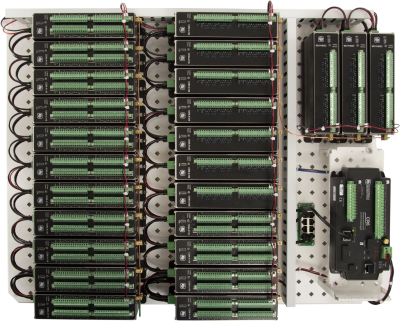
The name “CDMs” refers to “Campbell Distributed Modules,” which are measurement devices that you can use in several ways to enhance your data acquisition system. For example, CDMs can greatly increase the channel count of your data loggers and allow you to make multiple measurements simultaneously with the data logger, rather than multiplexing one measurement at a time. CDMs also add data logger functionality, such as vibrating wire capability (CDM-VW300 and CDM-VW305), and in some cases, CDMs can improve the measurement precision and resolution of your system.
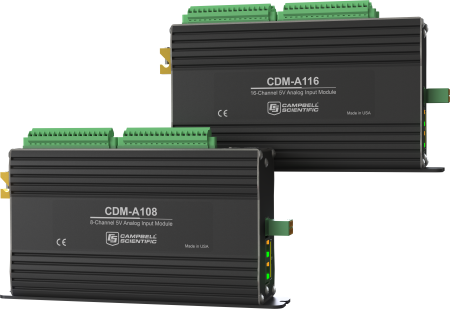
As an example of CDM resolution capability, the new CDM-A108 and CDM-A116 analog input modules make 24-bit ADC resolution, low-noise, high-precision analog measurements. These CDMs offer better resolution than can be achieved by direct measurements on the CR1000 datalogger (13-bit ADC resolution) or the CR3000 Micrologger (16-bit ADC resolution), and matches the resolution of the CR6 datalogger.

The CDM-A108 and CDM-A116 also add excitation channels, 12 V and switched 12 V ports for powering peripherals, and switched 5 V ports for peripheral control.
With CDMs, you can have a whole network (8 or more modules) that behave as a single data logger!
|
Recommended for You: To learn more about the CDM-A108 and CDM-A116, review the product brochure. |
What do you need to make a CDM work?
A CDM communicates with a data logger via a CPI (CAN Peripheral Interface) bus.
- When using a CR6 datalogger, a CDM connects directly to the data logger via the CPI port and a standard CAT5e Ethernet cable.
- To use a CDM with a CR1000, CR800, CR850, or CR3000 datalogger, a SC-CPI Datalogger-to-CPI Interface must be used between the data logger and the CDM.
What is CPI?
The CAN Peripheral Interface (CPI) is a proprietary measurement bus that provides communication between Campbell Scientific data loggers and CDMs. A major advantage of Campbell Scientific’s CPI protocol is its ability to communicate between devices over long distances at high rates with a variety of physical network topologies.
|
Recommended for You: To learn more about the CPI bus and how to design a CDM network, read the “Designing Physical Network Layouts for the CPI Bus” technical paper. |
How do CDMs differ from SDMs?
“SDMs” are “Synchronous Devices for Measurement,” which expand digital control ports, analog output ports, and measurement capabilities of data loggers. Similar to CDMs, SDMs are addressable devices, allowing you to connect more than one to a data logger at the same time. However, CDMs operating over a CPI bus can function at much higher speeds and greater distances than SDM networks. For example, the maximum cable length for typical SDM devices is six meters or less. In contrast, CDM devices can operate with cable lengths of several hundred meters, depending on network topology, termination, and baud rate. The “Designing Physical Network Layouts for the CPI Bus” technical paper discusses factors that limit distance and baud rate in a CPI network.
Despite some obvious advantages of CDMs over SDMs, SDMs still play an important role in expanding data logger networks.
How do CDMs differ from multiplexers?
Many Campbell Scientific users are familiar with multiplexers. A multiplexer (such as an AM16/32B or AM25T) also enables a data logger to measure more sensors. There are, however, some advantages of CDMs over multiplexers, including the following:
- CDMs offer increased measurement precision and lower measurement noise.
- Measurements are made in parallel with the data logger when running in PipeLineMode (that is, measurements are made on the data logger and on one or more CDM at the same time).
- CDMs can make high-speed measurements (up to 30 kHz maximum burst sample rate) that cannot be achieved with a traditional multiplexer.
- It is easier to program the CDMs relative to a multiplexer.
An Example of CDM Programming Simplicity
To understand how CDMs are simpler to program than multiplexers, let’s look at an example. To measure sensors of different types on a multiplexer, different measurement instructions are used within successive program loops. In contrast, no program loops are required for CDM measurements. Instead, the CDM-A108 or CDM-A116 uses the same measurement instructions as the data logger—just with the module type and module address added.
For example, the VoltDiff() instruction on a CR6 datalogger looks like this:
VoltDiff( Dest, Reps, Range, DiffChan, RevDiff, SettlingTime, fN1, Mult, Offset )
On a CDM-A108, the instruction becomes CDM_VoltDiff():
CDM_VoltDiff( CDMType, CPIAddress, Dest, Reps, Range, DiffChan, RevDiff, SettlingTime, fN1, Mult, Offset )
You’ll notice that the only difference between these instructions is that the CDM_VoltDiff() includes a module type (CDM-A108 or CDM-A116) and a CPIAddress (valid range is a number between 1 and 120). Hence, it is quite easy to add CDM measurements to your existing CRBasic program. (See the CRBasic Editor Help files for instruction details.) You can also easily generate programs with CDM instructions using our Short Cut Program Generator for Windows.
Conclusion
With CDMs, you can expand the capability of your data acquisition system. For example, you can use CDMs to do the following:
- Increase the channel count of your data loggers
- Add data logger functionality (such as vibrating wire capability)
- Improve the measurement precision and resolution of your system
While CDMs share some similarities with SDMs and multiplexers, CDMs offer some unique advantages. A major advantage of a data logging system using CDMs rather than multiplexers is that with CDMs, the system can make simultaneous measurements from multiple modules spread around your test site with high precision and speed. In contrast, a multiplexer can only make one measurement at a time. A major advantage of CDMs over SDMs is that the CDM modules can make measurements much faster and over much greater distances than SDMs.
I hope this article has helped you understand what CDMs are and how they can help you, as well as the differences between CDMs, multiplexers, and SDMs.
If you have any questions or comments about CDMs and using them in your applications, post a comment below.


 Dr. Carolyn Ivans is the Technical Communications Manager at Campbell Scientific, Inc. She has a doctorate in Ecology, Evolution, and Conservation Biology from the University of Nevada, Reno. She enjoys working with the Technical Communications team, product developers, and customers to create documentation and tutorials for Campbell Scientific products. In her spare time, Carolyn enjoys kayaking, hiking, and bike rides with her family.
Kommentare
Please log in or register to comment.