Kontrolliert Spannung und Stromstärke zum Schutz der Batterie


Überblick
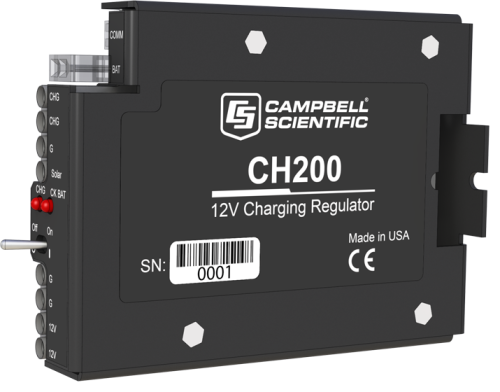
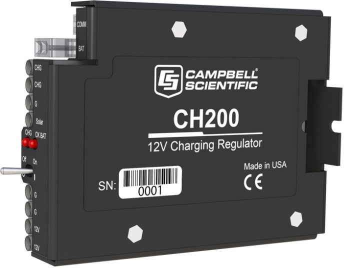
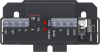
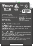
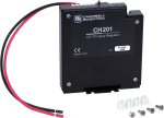
Der CH200 ist ein Laderegler, der mit einem Mikrokontroller ausgerüstet ist. Er sorgt für optimale Batterieladung von einer Solarzelle oder einem Netzteil und misst gleichzeitig mehrere Statusparameter zur Überwachung der Batterie.
This featured product was part of the Aconcagua expedition to install a weather station on South America’s tallest peak. Learn more about the expedition on our Extreme Application Series: Aconcagua page.
Lesen Sie mehrFunktionen und Vorteile
- Kann von verschiedenen Quellen geladen werden, Solarzellen oder Steckernetzteil
- Gleichzeitiger Anschluss von zwei Ladungsquellen möglich, z.B. Solarzelle und Netzteil
- Zweistufige konstante Aufladung und Temperaturkompensation optimieren das Laden und verlängern das Leben der Batterie
- Battery reversal protection
- Schützt die Stromversorgung vor Schäden durch zu hohe Spannungen oder Ströme
- Schützt die Stromversorgung vor Schäden durch Überspannung oder zu hohe Ströme
- Kann Last und Batteriestrom überwachen
- Echtzeitmessung der Ladespannung, der Batteriespannung, der Bordtemperatur, des Batteriestroms und der Last
- Für dieses Produkt ist eine verlängerte Garantiezeit möglich.
Bilder


Technische Beschreibung
The CH200 has two input terminals that enable simultaneous connection of two charging sources. It also incorporates a maximum power point tracking algorithm for solar inputs that maximize available solar charging resources. RS-232 and SDI-12 terminals allow the CH200 to convey charging parameters to a datalogger.
The CH200 has several safety features intended to protect the charging source, battery, charger, and load devices. Both the SOLAR – G and CHARGE – CHARGE input terminals incorporate hardware current limits and polarity reversal protection.
A fail-safe, self-resettable thermal fuse protects the CHARGE – CHARGE inputs in the event of a catastrophic AC/AC or AC/DC charging source failure. Another self-resettable thermal fuse protects the 12 V output terminals of the charger in the event of an output load fault.
The CH200 also has battery reversal protection, and includes ESD and surge protection on all of its inputs and outputs.
Kompatibel mit
Please note: The following shows notable compatibility information. It is not a comprehensive list of all compatible products.
Miscellaneous
| Product | Compatible | Note |
|---|---|---|
| 34029 |
Additional Compatibility Information
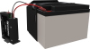
Batteries
The CH200 can charge the following battery families: EnerSys Genesis NP Series (includes our PS200, BP12, and BP24), EnerSys Cyclone Series, Concorde Sun Xtender Series (includes our BP84) and a custom battery.
Spezifikationen
| Operational Temperature | -40° to +60°C (VRLA battery manufacturers state that “heat kills batteries” and recommend operating batteries at ≤ 50°C.) |
| Dimensions | 7.5 x 3.7 x 10 cm (3 x 1.5 x 3.9 in.) |
CHARGE - CHARGE Terminals (AC or DC Source) |
|
| AC | 18 to 24 VRMS (with 1.2 ARMS maximum) |
| DC | 16 to 40 Vdc (with 1.1 Adc maximum) |
SOLAR Terminals (Solar Panel or Other DC Source) |
|
| -NOTE- | Battery voltages below 8.7 V may result in less than 3.0 A current limit because of fold-back current limit. |
| Input Voltage Range | 15 to 40 Vdc |
| Maximum Charging Current | 4.0 Adc typical (3.2 to 4.9 Adc depending upon individual charger) |
Quiescent Current |
|
| No Charge Source Present | 300 μA maximum |
| No Battery Connected | 2 mA maximum |
Battery Charging |
|
| -NOTE- | Two-step temperature-compensated constant-voltage charging for valve-regulated lead-acid batteries; cycle and float charging voltage parameters are programmable with the default values listed. |
| CYCLE Charging | Vbatt(T) = 14.70 V - (24 mV) x (T-25°C) |
| FLOAT Charging | Vbatt(T) = 13.65 V - (18 mV) x (T-25°C) |
| Accuracy | ±1% (on charging voltage over -40° to +60°C) |
Power Out (+12 Terminals) |
|
| Voltage | Unregulated 12 V from battery |
| 4 A Self-Resettable Thermal Fuse Hold Current Limit |
|
Measurements |
|
| -NOTE- | At -40° to +60°C |
| Average Battery Voltage | ±(1% of reading + 15 mV) |
| Average Battery/Load Current Regulator Input Voltage |
±(2% of reading + 2 mA) Impulse type changes in current may have an average current error of ±(10% of reading + 2 mA). |
| Solar |
±(1% of reading - 0.25 V) / -(1% of reading + 1 V) 1.0 V negative offset is worst-case due to reversal protection diode on input; typical diode drop is 0.35 V. |
| Continuous |
±(1% of reading - 0.5 V) / -(1% of reading + 2 V) 2.0 V negative offset is worst-case due to two series diodes in AC full-bridge. Typical diode drops are 0.35 each for 0.7 V total. |
| Charger Temperature | ± 2°C |
Dokumente
Broschüren Produkte
Handbücher
Realisierte Projekte
Übereinstimmung mit Richtlinien u. Vorschriften
FAQs für
Number of FAQs related to CH200: 3
Alle anzeigenWenige anzeigen
-
The CH200 or PS200 will pull power only from the source with the highest voltage at that moment. For example, the regulator will take the 20 W input from the 24 Vdc wall transformer rather than from the 18 V 50 W solar panel—even during the day. If the power goes out, the 50 W solar panel will charge during the day with no charging at night.
-
The CH100 is a float-only charger that is limited to a 20 W solar panel and a maximum load of approximately 1 A.
The more advanced (and more expensive) CH200 is a multistage controller that can charge at higher rates and use larger solar panels (90 W) while delivering a maximum of approximately 4 A to the load, depending on the temperature. The CH200 is a smart charger that incorporates MPPT technology (maximum power point tracking) and can be interrogated by the datalogger to check its state, solar panel status, load currents, battery voltage, and net battery current. In this regard, the CH200 acts as a high-tech sensor, as well as a charge regulator.
The CH100 has a temperature sensor for temperature compensation. The CH200 has a similar onboard temperature sensor, but it is more efficient and does not dissipate as much heat with a similar load. The CH200 also has a feature where an independent battery temperature measurement can be sent to the charger rather than using its onboard temperature sensor.
Anwendungsbeispiele
Overview Iraq’s Ministry of Agriculture has deployed a nationwide network of solar-powered, satellite-linked agrometeorological stations. The......lesen Sie mehr