How to Select the Correct Pulse Type for Your Measurements
von Jacob Davis | Aktualisiert: 04/21/2016 | Kommentare: 0

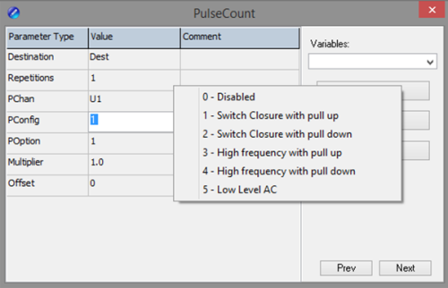
Have you ever had a sensor work on a P (pulse) data logger terminal, but not on a C (control) terminal? Is the list of choices for the PConfig parameter in the PulseCount() instruction daunting? Campbell Scientific data loggers offer several options for measuring pulse signals. Our Short Cut Program Generator will select the right option for you in the case of directly supported sensors. For other sensors, you must determine the correct option to choose in the parameter available in either PulseCount() in CRBasic or a generic pulse sensor in Short Cut. The correct option must be chosen for the pulse terminal to properly measure the signal.

This article will explain the differences in the options, so the next time you connect a pulse sensor, it should be simple. Beware that this article’s information will get a bit technical, but it will get directly to the point.
Matching Sensor Pulse Types with Data Logger Terminals
There are three main types of pulses:
- High frequency
- Switch closure
- Low-level AC
Check the documentation for your sensor so you know which type of output it has. The CR6 datalogger has U terminals that can be configured for any pulse type. Other data logger models have terminals dedicated for different types of pulses. Your data logger specification sheet will indicate which terminals can measure the pulse type you are interested in.
High Frequency (or Square Wave)

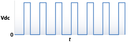
High-frequency pulses are often called square wave. The voltage on the line quickly rises to a set value, such as 5 V. The voltage remains high for a set amount of time then quickly falls to a neutral value, usually ground. The voltage pulses look roughly rectangular, like a series of square- or rectangular-shaped waves. A large variety of sensors have this type of output.
A terminal that measures a high-frequency pulse typically uses a pull-down resistor. The pull-down resistor ensures that a clean 0 V is present between pulses, thus providing resistance to electrical noise. C terminals on Campbell Scientific data loggers have internal 100 kohm pull-down resistors. Depending on the data logger model you have, other terminal types may also be able to read this type of pulse.
Switch Closure

Switch-closure outputs do not actively drive a pulse. A switch closure is simply a mechanical switch to complete a circuit. Rain gages typically have a switch-closure output. Some flow meters and anemometers also use this type of output.
A voltage applied on one wire makes a pulse appear on the other wire when the switch is closed. Power needs to be placed in the circuit with a pull-up resistor. The pull-up resistor provides power to the circuit, while limiting current to protect the switch. P terminals set to switch-closure mode use an internal pull-up resistor. You can often use other terminals by adding an external pull-up resistor. Refer to your data logger manual if you need to measure more switch closures than you have P terminals for.
Because the switch is mechanical, the actual metal contacts bounce when they slam closed. The bounce creates a series of fast spikes at the start of the pulse. The signal must be “debounced” so that the spikes are not counted as separate pulses. Debounce filtering is done either with an RC circuit or with software timing.
Low-level AC

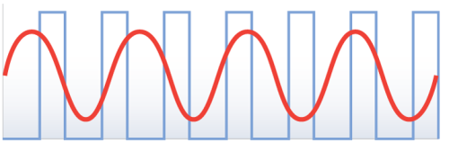
Low-level AC pulses are signals that swing between a positive and a negative voltage. The wave form looks sinusoidal. This type of pulse is typically seen as the output of many anemometers. Special circuitry is needed for reading low-level AC signals. The P terminals on the CR1000 datalogger and the even-numbered U terminals on the CR6 datalogger have the needed circuitry for direct connection. The CR300, CR310, and CR200X-series dataloggers have a dedicated P_LL terminal. You can use an LLAC4 module to convert low-level AC signals to square-wave pulses when you need to connect additional anemometers.
Other Pulse Types
In addition to the three main types of pulses, there are some other variations to be aware of.
Open Collector and Open Drain
Open Collector and Open Drain pulse-type outputs are switch-closure outputs that use a solid-state switch instead of a mechanical one. Because the switches are not mechanical, debounce filtering is not needed. Open Collector and Open Drain can be successfully read as switch-closure pulses. If the frequency would exceed the limit of switch closure, you may read them as high-frequency pulses with a pull-up resistor.
Period Average Measurements
A period average measurement measures the time needed for a set number of pulses to be received. Rather than a PulseCount() instruction, which measures continuously, a period average measurement is done over a short timeframe. On Campbell Scientific data loggers, period average measurements are performed on analog input terminals.
|
Recommended for You: If you need to perform a period average measurement, refer to the CRBasic Editor Help file for the PeriodAvg() instruction. To access the file, highlight PeriodAvg in the instruction list, and click the Help button above the list. For assistance with accessing the CRBasic Editor Help file for a particular instruction, watch the "CRBasic | Help System" video. |
Conclusion
Campbell Scientific data loggers are capable of measuring all the main types of pulses. Measuring the signal successfully is a matter of selecting the proper terminal for the connection and the proper option for the PulseCount() instruction in your data logger program. If you have ever encountered a type of pulse output not covered by this article, please post a comment below.


 Jacob Davis is the Director of Client Services and Support at Campbell Scientific, Inc. He works with the worldwide technical support teams. His specialties include serial communications and advanced data logger programming. Jacob has a master’s degree in hydrology and worked with large irrigation projects before coming to Campbell Scientific, Inc.
Kommentare
Please log in or register to comment.